Latching Relay Remote Control (LRR)
£74.00 (ex. VAT)
Description
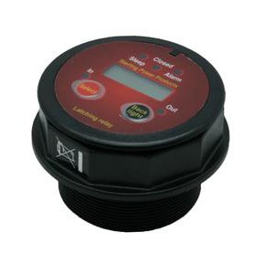
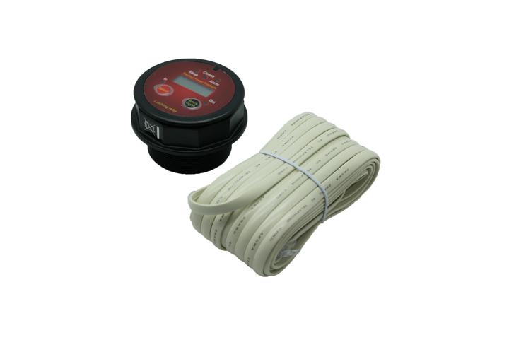
Latching Relay Remote Control
Optional remote control for Pro Latch R – features include: LCD displays can be selected to show input voltage or output voltage. Other alarms/information displayed via LEDs would be: High voltage trip alarm (showing if fault on input or output) alarm set at 16V (x 2 for 24V), Relay engaged or disengaged – Emergency override function (hold select button for 5 sec to give 1 min override) – Audible alarm function disengage (especially boat or camper vans would not want alarms going off at 4 in the morning). Background light on/off (background light changes colour with cycle), red = warning, blue for online, green for offline – Sleep mode indicator – 1 min safety / latch override ability.
Suitable for use as one of the following:
1) Split charger (VSR) relay / uni + bidirectional
2) Battery protect relay (over discharge and over charge)
3) Engine Start Protect relay
Why a latching relay over a conventional relay?
A conventional relay
A conventional relay (Such as ones used in cars to switch on your lights or control power distribution on boats etc.) These are by far the most common forms of relays produced. They are very reliable and relatively low cost yet inefficient. For instance, a standard 80A/12V relay would consume about 0.45A (staying on). So, with a 70A alternator the consumption of 0.45A for the relay is of no real importance. However, if you are planning on using a 60W solar cell on a normal ‘English’ day you would expect approximately 0.4A of current. All of which shall be lost across the relay, thus, rendering the solar cell useless. So lets do the maths. With the engine off, a single conventional relay will consume in 1 day 0.45A x 24 hrs =10.8A. Per week = 75.6A.
A latching relay
A latching relay works in a completely differently way. Instead of using power to “stay on “ it locks into position. So no matter if the circuit is ‘on’ or ‘off’ it engages a locking device (latch). This consumes no power to hold that position. On the down side they cannot be used straight out of the box like a standard relay. This is because they need a control circuit to work the internal latching device.
It only needs a short burst of power to pull the contacts from one side to the other. Then the power must be removed, this, in itself, needs a control circuit. Sterling’s efficeincy is down to 0.0005A (0.5mA) where our competitors are at 4-12mA. So lets do the maths. With engine off our latching relay with active control circuit will consume 0.0005 x 24hrs = 0.012A per day which is 0.084A per week. Compared to a standard relay which uses 75.6A in a week a latching relay system will use nearly 1000 times less, and this is for only 1 relay, what happens if you need 2,3 or 4 on a larger installation, clearly this low power consumption latching relay is the only sensible choice if solar or wind is used to supplement the main alternator charging system.
12V or 24V auto selected
12V or 24V is automatically selected by the product, If less than 16.5V is detected then the unit will power up as 12V, if more than 17V the unit will power up as 24V.
Fine voltage key trigger point adjustments, each function has factory preset voltage trigger points these trigger points can be customised. A magnetic swipe can be used to adjust from 10.4V- 15 V for ‘on’ voltages ( x 2 for 24V ) and 10.0V- 14.6V for ‘off’ voltages (x2 for 24V). You would perhaps customise these settings for lithium batteries.
Pre set voltage can be adjusted if required.
| Max | Quiescent | |||||||
| Part | Continuous | Intermittent | Current | Input | Output | Battery | Starter | Charging |
| Number | Current | Current | mA | Voltage | Stud | Protect | Protect | Mode |
| LR80 | 80 | 500 | 0.5 | 12/24 auto | 6mm | off 10.9V | off 12.4V | on 13.3 |
| on 12.8V | on 13V | off 12.9 | ||||||
| LR160 | 160 | 1000 | 0.5 | 12/24 auto | 8mm | off 10.9V | off 12.4V | on 13.3 |
| on 12.8V | on 13V | off 12.9 | ||||||
| LR240 | 240 | 1500 | 0.5 | 12/24 auto | 8mm | off 10.9V | off 12.4V | on 13.3 |
| on 12.8V | on 13V | off 12.9 | ||||||
| LRR | latching | with 5m | for longer | standard | telephone | extension | ||
| relay remote | of cable | use | cable |
1) Bi-directional + uni directional charging:
(default voltage setting, on 13.3V, off 13.0V x 2 for 24V ) If, after the engine is switched ‘off’, and there are solar cells or wind charging systems in the boat/vehicle then the ability to charge other battery banks becomes very important. Therefore, the power consumption of the splitting device becomes extremely important and so the latching relay comes into a world of its own.
There is no limit to how many battery banks that can be charged. An instant starter disengage circuit is built in to prevent starter motor high current surge damaging the product. This open circuits the relay between activating the starter motor and the bendix engaging the fly wheel. On Charge Mode the unit is preset for either side activation, i.e. whichever side of the relay reaches the trigger voltage first will activate the relay in that favoured direction. For uni-directional the relay will only be activated by a voltage in excess of 13.3V (x 2 for 24V). This is on the input cable stud only,. The output cable voltage will not activate the product. In the event that you need the output cable to do the activation simply reverse the cables.
2) Battery Protection Mode:
(default setting, ‘off’ 12.0V, ‘on’ 12.3V x 2 for 24V). The battery protect system, protects a battery bank from premature and expensive destruction due to deep discharge or over charging. It only takes one accidental deep discharge of a battery bank to destroy that battery bank. A very expensive mistake indeed. This is most common on things such as hire boats or hire equipment.
This leaves the owner with a large battery replacement bill. The battery protection relay disconnects the batteries at a preset limit in order to protect the battery bank. The unit has a built in warning system, i.e. it will switch the power off for 10 secs then back on for 1 min to give a reasonable warning to allow the operator time to complete a process, such as: start the engine or activate a battery charger to take place to help the situation (i.e. recharge the batteries). This could happen on a boat late at night so the extra minute allows someone to start the engine to recover the batteries. The remote control is an essential requirement to reactivate the Pro Latch R after the relay has tripped. For extra safety, the optional remote control gives the option to override the trip for 1 min in the case of emergency.
Remote isolation mode: by using the remote control the battery bank can be manually isolated if required.
3) Engine Start protection mode:
(default setting ‘off’ 12.4V & ‘on’ 12.6V ). This mode is designed to allow products to be safely run from an engine starter battery and to disconnect the product at such a stage as to allow the engine starter battery to retain enough power to ensure the engine will start.


