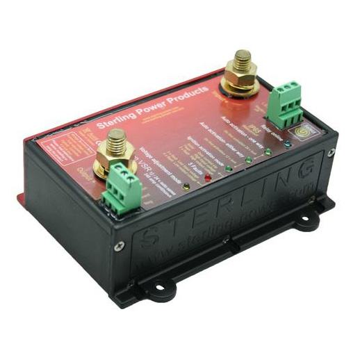
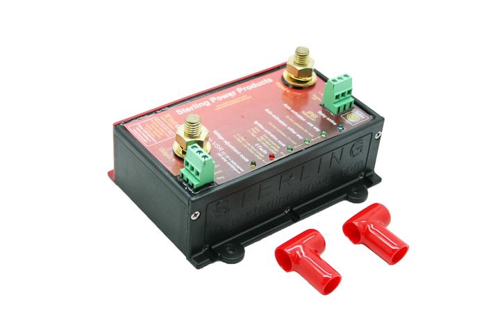
Voltage Sensitive Relay Pro Connect VSR
£63.36 – £86.59 (ex. VAT)
Description
r iVoltage Sensitive Relay Pro Connect VSR 80, 160 & 240 amp
| DC Voltage | Amps | Size L x W x D mm | Weight | Part Number |
| 12 & 24 auto | 80 | 140 x 180 x 40 | 0.1 kg | VSR80 |
| 12 & 24 auto | 160 | 140 x 190 x 40 | 0.2 kg | VSR160 |
| 12 & 24 auto | 240 | 140 x 200 x 40 | 0.25 kg | VSR240 |
Voltage Sensitive activated relays:
This product would be regarded as the next level up from the signal feed relay. The main difference being that it is totally automatic – this relay does not require an ignition feed to operate. It works on monitoring the input voltage to the device. (Usually the starter battery or battery bank with other charging source such as a battery charger or wind gen). When this voltage exceeds 13.3V the processor makes the assumption that the alternator / battery charger or other power device is active. As such it will automatically engage the relay to connect the main battery bank to the auxiliary battery bank and so charge the auxiliary battery.
Conversely, when the voltage drops below 12.9V the processor in the relay assumes that either the engine has been stopped or the load on the aux battery is pulling the starter battery down too much and for safety reasons it should be isolated. In a nut shell this is easier to install than the above and is smarter. However, it has some of the same limitations as the standard signal relay.
Ideal applications:
See signal relay applications. Also ideal for charging a secondary battery bank from a battery charger which has only one output such as combined inverter charger. The starter motor interlock connection prevents the starter motor current being pulled through the relay and damaging the relay.
Its limitations:
See the limitations for the signal relay. Another major problem with standard relays is their ability to switch off under high load. The main job of a voltage sensitive relay is to sense any major current being taken out of the starter battery (primary) and to stop it. For example, if we take a typical 12V boat system with an 80A alternator and install a standard 80A VSR on the engine starter battery bank to charge the secondary battery (domestic battery bank, anchor winch or bow thruster battery bank).
On engine start up the alternator will raise the voltage on the starter battery. This will engage the relay to charge the secondary battery bank (so far so good). However, for the sake of argument say the secondary battery bank is discharged. (i.e. first thing in the morning). Then someone switches on a 2000W inverter, or a bow thruster or the anchor winch. These items will attempt to draw 200A + from the secondary battery bank. However, because the secondary battery is nearly empty, the load (200 amps) will automatically attempt to draw this current from the highest voltage source. Which, in this case, would be the starter battery bank.
Obviously we do not want this to happen as we do not want to drain the starter battery or burn out the 80A relay or even worse set fire to the cables because you are now trying to pull 200A plus down these cables. In theory the large current flow through the VSR will drop the starter battery voltage and so trigger the relay to open circuit and so switch off this circuit stopping the drain and saving the day.
However
A relay has 3 main ratings, for example, an 80A relay can take 80A all day no problem, (hence its continuous rating) and has a short term overload of about 400A for about 1/10th sec. It has a third rating, however, that is much more important. That is the maximum current it can open circuit at.
The assumption by the public is that an 80A relay can open circuit at 80A. But that is not so, it has an open circuit current rating of about 30-40A. And so the problem becomes apparent. The high load on the secondary battery system (in the above example) causes an instant load of 200A + on the relay. (That’s ok, it can deal with this for a split second) then the control circuit attempts to open the relay to stop this discharge. Then BANG you open the relay with 200A going through it (with an open circuit rating of about 40 amps). So then you cause a large back E.M.F. If you’re lucky, it will vaporise the contacts blowing them in to small pieces and open circuit the relay destroying the product.
To reduce this effect, Sterling puts anti back E.M.F. spark reducers on all relay products.
Adjustable:
This unit comes factory set to bi-directional activation and can be fitted with no adjustments required to operate as a Voltage sensitive relay straight out of the box. It is auto voltage adjustment. So it can be fitted to a 12 or 24V circuit. However, the following things can also be adjusted if desired.
Unit directional activation:
Function 1:
Charging activated by starter battery voltage increase (engine on). This is the most common setting and the factory default setting. This setting also does not have an ignition feed requirement. This connects the primary and secondary banks based on a voltage in excess of 13.3V being sensed on the primary battery only (the engine starter battery). The 2nd battery bank, once connected would only disconnect when both battery banks drop below 13.0V on both sides. The 13V safety threshold is still activated to protect and seperate the batteries if, or when, the drain that invoked this function (voltage drops below 13V). Once the unit has tripped, will not re-engage until the voltage on the primary battery bank (the engine start) has exceeded 13.3V again. No ignition feed required on this setting.
Function 2:
Charging either way (bi directional), based on a voltage rise on either side of the unit (default setting). This function will close the relay at 13.3V sensed on either side of the relay. A good example of this would be the use of a combi inverter charger on the domestic battery bank. Because most combi’s only have a single output charging line (to the domestic battery bank) then with this function the unit will charge from the combi to the starter battery bank. (In effect giving you 2 outputs from the battery charger) when the combi is on. But also charge from the alternator to the domestic battery bank when the combi is off. In either mode the unit still has the 13.3V on and 13V off mode and the current limit function. No ignition feed required on this setting.
Function 3:
Charging batteries one way only. This function allows a charge to flow from the alternator, or battery to battery charger, or any other charging source to a secondary battery bank. But only when the engine is running. In effect, this mode only allows current flow from the primary source to the secondary. It will continue to flow until either there is an overload threat or a low voltage threat to the primary battery or the engine is shut down. This function requires an extra wire to the unit. An ignition feed, that informs the unit if the engine is running or not.
Voltage parameter activation:
Voltage activation and deactivation parameters can be adjusted using the setup command.
Auto 12/24V selection. The unit will auto select the system voltage using the following. If it senses 4 to16V it will lock to 12V. Of it sees 16-30V it will lock to 24V. Or if for some reason the input voltage is very low (in the case of an empty 24V system), then the product can be disconnected and allowed to re-engage. Once locked the product will hold that setting until fully isolated again.
Both the VSR and the CVSR unit are fitted with the latest active progressive disconnect algorithm. This is to ensure that the batteries can charge even where large differential voltages exist. As such there will be various time delays between what the customer has preset as the turn ‘off’ voltage point and the product actually turning off. The time delay will reduce the lower the voltage is below the programmed disconnect voltage.
Features
| 0.01 volt drop | Ignition feed (not always required) |
| Waterproof to IP65 | SAEJ1171 ignition protected |
| High overload surge rating | Back EMF spark arrester |
| Remote LED connection | No ignition feed voltage drop |
| Suppression diodes across relay to prolong life | Time delay to prevent engine starter damage |
| Single & Twin starter motor disengage connections | 12V & 24V automatic selection |
| Extremely low quiescent current approx 1 mA | Custom voltage adjustment parameters available |
| Active progressive disconnect algorithm | Automatic voltage activation |
| Automatic voltage de activation | Protects primary battery from discharge |
| Emergency auxillary forced activation | High battery voltage trip protected |
| 5 LED information display | 5 alarm functions and safety trips plus information |
| Adjustable relay trigger side operation | Short circuit protection (prior to engagement) |
Which model suits my needs best ?
1) The first part is easy, what is the max size of your alternator or charging device. I.e. do you have a 90A alternator or a 100A battery charger charging the primary battery bank. This means that the secondary battery could be subjected to at least that load. So, the relay must be able to comfortably handle that sort of current continuously. It would be wise to give the relay a good 10-20% comfort zone, i.e. always up-size the relay if the charging source and relay are the same. For example, if you have an 80A alternator, combi or battery charger with an 80A relay then go to the 160A relay option to be safe.
2) Next its cost of installation and ease of installation. If you are fitting the unit and access to ignition feeds is simple then the Ignition Feed system should be entertained. However, if not then the Voltage Sensitive Relay version is much simpler to fit and totally automatic, and has a lot more functions.
3) Do you need to vary which side of the relay activates the unit? or even ensure the unit is isolated? (via ignition feed, or even adjust the standard voltage parameters, all this is possible on the Voltage Sensitive Relay).
4) The last, but most important aspect is safety. The most important thing here is to establish what the maximum possible load is that could be placed on the secondary battery bank when the relay is engaged. I.E. a large inverter / anchor winch, bow thruster. Remember that every load you put on, the secondary battery will have a percentage of this load transferred to the primary battery. This depends on how full the secondary battery is.
This could range from a few percent to 100 percent. So, it is important that the relay system can deal with this high load without damage. If there are large potential loads such as hundreds of amps then the only way to do this is using a Current Limiting Voltage Sensitive Relay. This is because when exposed to excessive currents, the current limiting models simply and safely shut down until the excessive current is removed, i.e. switched off. Then it can automatically re-instate itself and carry on after that large surge load has stopped. This removes the need for excessive cabling and ensures a safe installation with less reliance on fuses for protection.


